

Why is the straight-ahead centre position important?
It establishes the cylinder travel available to the left and right. Confirm centre and both lock positions so the linkage, not the cylinder ends, defines the steering limits.

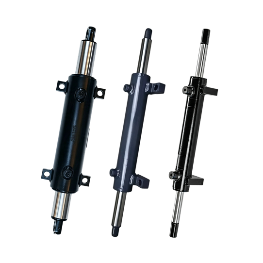
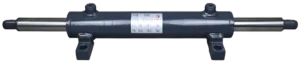
An aerial lift steering cylinder moves the steering linkage on a mobile work platform. Its stroke and centre position must correspond with the axle geometry so the wheels reach the required left and right angles without forcing the cylinder or tie-rod beyond their working travel.
We review the cylinder as part of your steering system. Send the platform model, axle or linkage drawing, steering angles and hydraulic information so we can check reference lengths, mounts, ports and available installation space before quotation.

Do not select a replacement from bore and stroke alone. The steering linkage and the cylinder must reach their limits together without bottoming, over-extension or side load.
| Item | What you should provide | What it establishes |
|---|---|---|
| Platform and axle | Machine type, model, steering axle drawing and whether one or both axles steer | Identifies the actual chassis layout and separates the inquiry from forklift steering-assist hardware. |
| Steering geometry | Wheel angles, steering-arm and tie-rod dimensions, pivot locations and cylinder attachment points | Allows travel and force direction to be reviewed through left lock, centre and right lock. |
| Cylinder lengths | Total stroke, equal or unequal rod travel, centre position and reference lengths at each steering position | Defines where the piston should sit at straight ahead and prevents either end from becoming the mechanical stop. |
| Mounting interfaces | Bracket spacing, pin or bolt sizes, rod-end threads, offsets, clearances and installed orientation | Confirms fit and alignment with the axle structure and steering linkage. |
| Hydraulic circuit | Working pressure, port thread and position, hose clearance, fluid, flow and steering-control schematic | Confirms connections and the circuit data needed to review movement in both directions. |
| Duty and environment | Steering cycles, travel speed, indoor or outdoor use, temperature, moisture, dust and salt exposure | Guides discussion of seals, wipers, rod finish and external protection for the machine environment. |
Share the axle and steering-linkage drawings, target wheel angles, available pressure and installation envelope. We can review stroke, centre position, reference lengths, brackets, ports and rod-end interfaces as one configuration.
If an approved drawing is unavailable, remove the cylinder and send its part number, clear installation photos and measurements at centre and both steering limits. We will identify missing dimensions before quotation.
Inspect pins, brackets, steering arms, tie-rods and axle pivots as well as the cylinder. Wear or bent linkage can change the required travel and introduce side load into a new cylinder.
It establishes the cylinder travel available to the left and right. Confirm centre and both lock positions so the linkage, not the cylinder ends, defines the steering limits.
Provide total stroke, rod positions at centre and both locks, overall reference lengths, bracket spacing, rod-end details, port information, bore and rod diameters, and clear installed photos.
No. This page covers chassis-steering cylinders for mobile aerial work platforms. A forklift steering assist cylinder works with a forklift steering linkage and has a separate selection intent.
Use the aerial lift cylinder page for platform or boom lifting and the aerial platform support-leg cylinder page for chassis stabilization. See the aerial work platform application for the wider system context.