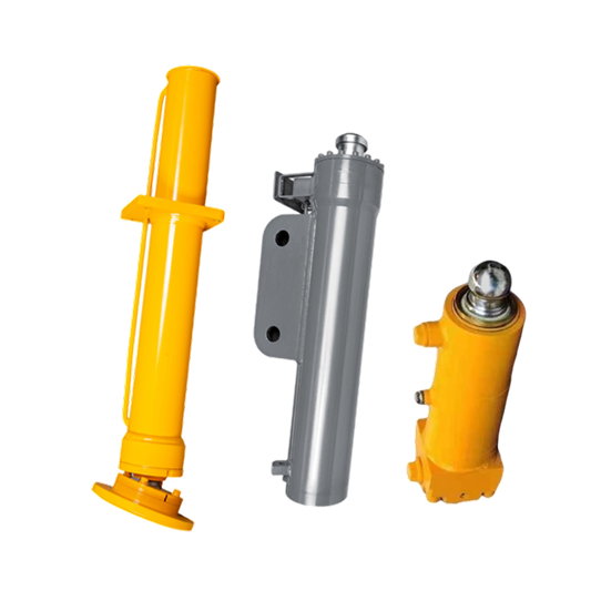
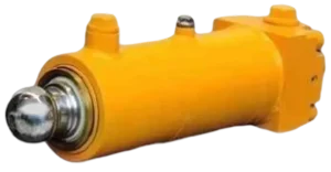
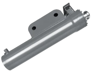
| Machine and support-leg layout | Machine type and model, number of legs, cylinder location, deployment direction and installed orientation | Confirms vertical construction-equipment support rather than an AWP stabilizer or horizontal outrigger beam. |
| Support reaction and load cases | Maximum load at each leg, machine mass distribution, working slope, lifting sequence and any dynamic or impact condition | Defines the load path used to review bore, rod, mounts and the required holding arrangement. |
| Travel and reference lengths | Stroke, retracted and deployed pin-centre lengths, ground clearance, leveling range and interference points | Confirms whether the foot reaches the support surface and retracts within the transport envelope. |
| Mounting and foot interface | Base mount, trunnion, clevis or flange details; pin sizes, widths, offsets, rod-end connection and foot-pad geometry | Allows both cylinder ends to be checked against the chassis and ground-contact structure. |
| Hydraulic and holding circuit | Working and peak pressure, port thread and position, flow, fluid, valve-block interface and hydraulic schematic | Confirms connection compatibility and the machine-specified method of holding the supported load. |
| Duty and environment | Cycle pattern, storage orientation, temperature, dust, mud, water, salt exposure and cleaning method | Guides discussion of seals, wipers, rod finish and external protection for your operating conditions. |