|
EN
Get a Quote

PDF/STEP

AUTOMATION LINE LIFTING CYLINDER

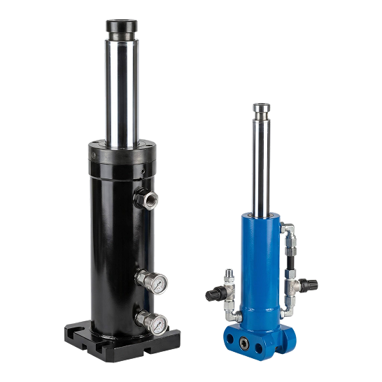
Raise a work carrier, fixture or tooling plate in an automated production line with a cylinder matched to your moving load, stroke, installed height, mount, pressure, speed, duty cycle and load-holding method.
Products
Lifting Cylinder
Lifting Cylinder
  • Applicable Tonnage: 0.05 ~ 2t
  • Bore Diameter: 25 ~ 80mm
  • Rod Diameter: 12 ~ 50mm
  • Stroke: 20 ~ 1200mm
  • Working Pressure: 4 ~ 16MPa
Image 90 (1)
Image 91 (5)
Cc8c3d4ff16c2a6feb77582d98c215be 1 (1)
D38118d4ee75de51a6ae93b05eb4dd12 1 (1)
Subtract (1)
OEM/JDM
Contact Us
PRODUCT
DESCRIPTION
  • Powering Industrial Intelligence Engineered for high-frequency and high-precision operations, our automation line cylinders are essential components for modern smart manufacturing. These compact and durable actuators provide reliable motion control for critical tasks such as material lifting, workpiece clamping, and high-speed sorting. Featuring advanced sealing technology and high-wear resistance, they are designed to perform consistently in 24/7 automated environments, ensuring maximum efficiency and minimal downtime.
Fixed production equipment

Configure the Lift Around Your Station

This automation line lifting cylinder supplies vertical motion for a work carrier, fixture, tooling plate or material-transfer station. We do not select it from tonnage alone. You send us the moving mass, center of gravity, required stroke, retracted and extended references, lift time, cycle rate, mounting interfaces and the required response to a pressure loss.

The cylinder should create axial force while the machine structure handles guidance and lateral restraint. If the load is offset, guided by rails or raised by more than one actuator, show us that geometry. We can then review the cylinder dimensions and interfaces against the mechanism instead of treating the actuator as a free-standing guide.

Work-carrier elevation

For a pallet, nest or carrier that moves between two fixed levels, state the carrier mass, maximum payload, center-of-gravity envelope and any process force applied while raised. Include the datum used for both end positions and identify whether the machine uses external hard stops.

Fixture or tooling lift

Show how the rod end contacts the tooling plate and how the cylinder base is attached. Give us the bolt pattern, pilot or register dimensions, available envelope and port access. A section view is especially useful when the cylinder sits inside a compact machine base.

Multi-point lifting

If two or more cylinders raise one frame, define the permitted height difference at every phase of travel. Tell us whether the mechanism, flow control, position sensors or machine controller manages synchronization; the acceptable skew is a system requirement, not only a cylinder dimension.

Replacement matching

For an installed unit, send the nameplate or part number, clear photographs, bore, rod diameter, stroke, closed and open reference lengths, mount dimensions, port specification and valve arrangement. When your current interface cannot be reused, our custom cylinder capability provides a separate drawing-based route.

The range shown in the existing specification block is a starting envelope, not an automatic selection. Your quotation drawing should confirm the rated moving load, pressure, dimensions, ports, mount, duty cycle and any load-control provisions for the actual station.
Drawing and RFQ inputs

Automation Lift-Cylinder RFQ Checklist

InputWhat you should provideWhy we review it
Moving assemblyFixture or carrier mass, maximum payload, center of gravity, friction and any process force applied in the raised position.Separates the moving load from side force, impact and other machine reactions.
Cylinder quantity and orientationNumber of cylinders, vertical or inclined installation, push or pull direction and a section view of the mechanism.Defines how load is shared and whether each rod remains axially loaded.
Stroke and height referencesUsable stroke, retracted and extended datum dimensions, approach clearance, overtravel allowance and external stop locations.Prevents a correct stroke from being paired with the wrong installed length.
Bore, rod and pressureAvailable working pressure, return pressure, requested bore and rod size when known, plus the design load or force case.Lets us check force direction, pressure basis and rod stability together.
Base and rod interfacesFlange or foot dimensions, bolt pattern, pilot diameter, rod thread or contact pad, alignment datums and allowable envelope.Controls fit, load transfer and service access inside the station.
Ports and plumbingPort standard, size, orientation, hose or manifold connection, valve location and clearance for fittings and tools.Avoids a port arrangement that conflicts with the frame or guarding.
Motion timingRaise and lower time, permitted acceleration and deceleration, available flow and required speed near each end position.Connects the cylinder volume to the valve, pump and machine cycle.
Cycle profileCycles per minute or hour, dwell under load, operating hours per shift, fluid temperature and ambient temperature.Gives us a measurable duty cycle for seal and thermal review.
Holding and failure responsePermitted drift, hold time, trapped-load case, pressure-loss response, guarding and any mechanical support or lock.Separates motion generation from the machine's load-holding and safety functions.
Environment and acceptanceFluid type, contamination exposure, washdown or dust conditions, finish requirement, inspection documents and test criteria.Defines materials, protection and the evidence required before shipment.
For the surrounding cell layout and related actuator functions, use our automation production-line application page. Keep each actuator's load case, dimensions and cycle data separate in a multi-cylinder project.
Before quotation

What We Check from Your Load Case and Drawing

Force and pressure basis

We compare the required push or pull force with the usable pressure range, return-side pressure and the machine designer's allowance for friction and acceleration. Tell us whether the stated load is normal, maximum or an abnormal case so the quotation is tied to the correct condition.

Rod extension and stability

A long extended rod behaves differently from a short compact installation. Give us the unsupported length, end restraint, mounting orientation and possible offset. We use those inputs to review rod diameter and the need for external guidance without assuming the rod can carry lateral machine loads.

Mounting and alignment

We check the base register, bolt pattern, rod-end contact and alignment datums shown on your drawing. If the machine frame can deflect or the guided table can bind, identify the expected misalignment and how the mechanism accommodates it before the interface is released.

Controlled lowering and holding

State the maximum lowering speed, permissible drift and what the station must do after loss of pump pressure or electrical power. The circuit designer can then define any load-control valve, monitored stop or mechanical support as part of the complete machine risk assessment.

Engineering questions

Automation Line Lifting Cylinder FAQ

What type of machine does this page cover?

It covers a fixed production cell where a hydraulic actuator raises a fixture, tooling plate, pallet nest or work carrier between defined positions. Your station drawing and load case remain the basis for the final configuration.

Can I select the cylinder only from the published tonnage?

No. Use that value as an initial range check, then provide moving mass, pressure, stroke, installed height, center of gravity, acceleration, orientation and duty cycle. The mechanism and failure response can change the required configuration.

Does the cylinder also guide the lifting table?

We recommend that the machine structure guide the table and resist moment or lateral force. Show the guide spacing and load offset so we can review how the actuator connects to the guided member and whether the rod remains axially loaded.

Will the load stay raised if pressure is lost?

Do not assume it will. Tell us the permitted movement, hold time and failure case. Your machine design may require a load-control valve, monitored position, guarding or a mechanical support independent of the cylinder seals.

How should I specify two cylinders lifting one frame?

Provide the cylinder spacing, load distribution, guide arrangement, required level tolerance and permitted skew during travel. Also state how the machine controls synchronization and what it does when one position signal or hydraulic path differs from the other.

What information is needed for a replacement?

Send the existing part number, clear installed and removed photographs, bore, rod, stroke, closed and open reference lengths, every mounting dimension, rod-end geometry, port details, valve arrangement, pressure and measured cycle time.

Send us the station drawing and lift cycle.Include the load case, height datums, mount, ports, timing, duty cycle and pressure-loss requirement.
Request a Drawing Review
PRODUCT
APPLICATION