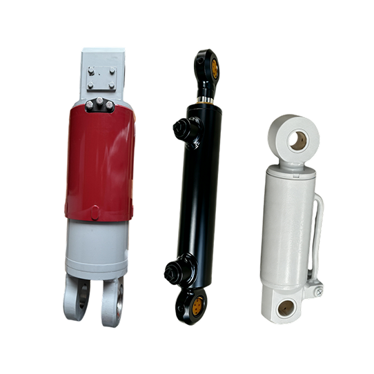
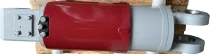
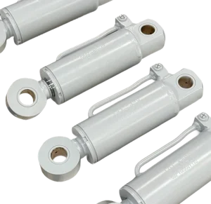



What does a construction equipment grab cylinder do?
It extends and retracts within the attachment linkage to open or close the grapple jaws or tines. The linkage converts cylinder travel and force into rotation at the grapple pivots.

A construction equipment grab cylinder connects to the hydraulic grapple or grab linkage. As the rod moves, the linkage rotates the jaws or tines between their open and closed positions. The cylinder's retracted and extended pin-centre lengths must agree with the pivot geometry so the attachment reaches both end positions without the cylinder or linkage becoming the mechanical stop.
We review the cylinder with your attachment drawing, not as an isolated bore-and-stroke item. Send us the carrier model, attachment type, pivot dimensions, required opening range, installed lengths, mount details, port orientation and circuit data. You can then confirm the interfaces and movement before we quote.

Outside appearance does not confirm whether a cylinder will fit a grab attachment. You need to relate its dimensions to the linkage at the fully open and fully closed positions, then check the mounts, pressure, ports, flow and hose path against the carrier. Use the following information for an OEM or replacement inquiry.
| Item | What you should provide | What it establishes |
|---|---|---|
| Carrier and attachment identity | Carrier type and model, attachment manufacturer and model, grapple or grab type, cylinder quantity and the movement this cylinder controls | Separates jaw actuation from boom, arm, bucket or other machine-cylinder functions. |
| Linkage and end positions | Pivot drawing, cylinder pin centres at both end positions, stroke, required opening width, closed position and the available installation envelope | Confirms travel and installed lengths without relying on the cylinder as the attachment stop. |
| Force and load case | Material handled, required gripping force or load at the jaw, linkage lever arms, working and peak pressure, and expected shock conditions | Provides the load path needed to review cylinder force and the attachment connection. |
| Mounting interfaces | Eye, clevis, trunnion or other end details; pin diameters, widths, offsets, bushings or spherical bearings and alignment tolerances | Checks whether both ends fit the attachment ears and remain aligned through the stroke. |
| Hydraulic circuit | Working and peak pressure, flow, fluid, port threads and positions, hose routing, and any valve block or manifold on the cylinder | Confirms the connection layout and the circuit information that affects movement and pressure control. |
| Duty and environment | Cycles per hour, impact frequency, temperature, dust, mud, water, corrosion exposure and cleaning method | Supports review of seals, wipers, rod finish and external protection for your actual duty. |
Share the carrier and grapple assembly drawing, pivot locations, working positions, load case, hydraulic schematic and cylinder envelope. We can review the bore, rod, stroke, installed lengths, mounting ends, ports and acceptance requirements as one configuration.
If an approved drawing is unavailable, send the existing part number, clear installed photos and complete measurements from the removed cylinder. Include retracted and extended pin-centre lengths, and identify which length corresponds to the fully open attachment position; overall body length alone is not enough to confirm the fit.
Inspect the pivot pins, bushings, mounting ears, jaw stops, hoses and attachment frame before replacing the cylinder. Worn pivots, a twisted frame or a seized joint can introduce side load. If paired cylinders move unevenly, record which side leads and inspect both linkages and the circuit.
It extends and retracts within the attachment linkage to open or close the grapple jaws or tines. The linkage converts cylinder travel and force into rotation at the grapple pivots.
The terms are often used for the same jaw-actuation function. You should still identify the carrier, attachment and exact movement because manufacturers may use different product names for similar mechanisms.
A grab cylinder actuates the grapple or grab jaws. Boom, arm and bucket cylinders move the excavator or loader linkage itself, so their load paths, geometry and installation interfaces are different.
Provide bore, rod diameter, stroke, retracted and extended pin-centre lengths, both mount details, pin sizes, bushing widths, port threads, port positions and the available clearance around the cylinder.
Usually not. One carrier can operate different attachments, and attachment revisions can use different cylinder geometry. Send the attachment model, existing part number, drawing or measured sample together with installed photos.
Browse our construction equipment hydraulic cylinders for boom, outrigger, support-leg and grab functions, or see the mini excavator attachment cylinder application page for compact equipment projects.