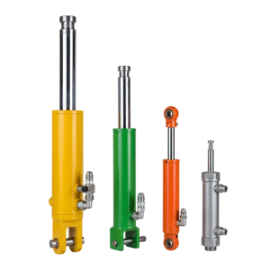


Clamp force
Confirm force at the workpiece after the fixture geometry and lever ratio are applied.

This clamping cylinder holds and releases workpieces in machining, assembly, welding or inspection fixtures. A custom hydraulic cylinder configuration can match the required force, travel, pressure, mounting space and cycle rate.
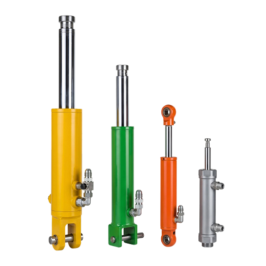
Confirm force at the workpiece after the fixture geometry and lever ratio are applied.
Check stroke, installed length, mounts, ports and clearance around the clamp arm.
Define clamp time, release time, permitted movement and the required holding method.
Use the table below to describe the workholding function. Broader station-level motion belongs on our automation production line cylinder application page; this product page stays focused on the clamping actuator and its fixture interfaces.
| Category | Requirements | Purpose |
|---|---|---|
| Fixture and process | Station type, workpiece, process step, cylinder quantity, clamp direction, direct or lever-driven action and the loading/unloading sequence | Defines what the actuator must hold, when it engages and when it releases. |
| Force and load path | Required force at the part, contact-pad location, lever dimensions, cylinder angle, friction, external process load and design margin used by your machine team | Provides the geometry needed to relate workpiece force to cylinder force. |
| Travel and envelope | Approach travel, clamp travel, total stroke, retracted and extended pin-centre or mounting-face-to-rod-end lengths and surrounding clearance | Confirms that the rod reaches both positions without the cylinder becoming the fixture's hard stop. |
| Mounting interfaces | Flange pattern, pilot diameter, clevis or trunnion dimensions, pin sizes, threaded interfaces, rod-end connection, alignment and side-load controls | Defines the mechanical connection and the datum used on the approved drawing. |
| Hydraulic circuit | Normal and peak pressure, available flow, fluid, port thread and orientation, valve arrangement, hose routing, release timing and required hold condition | Connects force, motion time and pressure retention to the actual circuit. |
| Duty and acceptance | Cycles per minute or hour, time clamped, ambient temperature, coolant, washdown, dust, weld spatter, inspection points and test criteria | Supports review of seals, rod surface, protection and your acceptance plan. |
We relate the requested clamp force to effective piston area, pressure at the cylinder, lever ratio, contact position and friction. Provide the force needed at the part rather than only the machine's pump-pressure setting.
We check total stroke together with retracted and extended reference dimensions. Separate rapid approach from the short clamping movement when your fixture uses both, and identify the fixed datum for every measurement.
We record flange, clevis, trunnion, pin, pilot, thread and rod-end details on the drawing. Port position must suit your hose path throughout the full fixture movement without twisting, rubbing or blocking service access.
Tell us the required clamp and release times, cycles per shift, dwell time, environment and planned quantity. We also need your dimensional, pressure, leakage and functional acceptance criteria before production release.
Send the fixture drawing with clamp force, travel, pressure, installed lengths, mounts and ports.
No. Cylinder angle, lever ratio, contact point, friction and available pressure also affect force.
Use fixed mounting datums and provide both retracted and extended reference dimensions.
Do not assume it will. Define permitted movement and the required valve or mechanical lock.