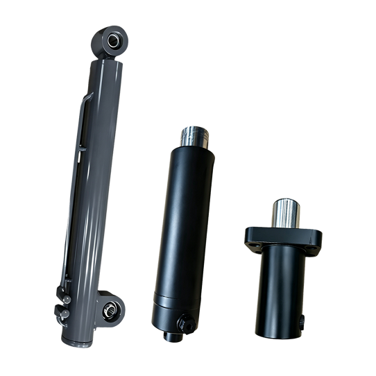


Module fit
Confirm stroke, closed height, mounts and port clearance from the assembly drawing.

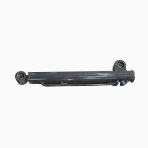
This cylinder raises a jacking deck, load platform or transfer interface. Selection is based on the lifted mass, mechanism, installed height, stroke, pressure and cycle time.
Confirm stroke, closed height, mounts and port clearance from the assembly drawing.
Define synchronization, permitted drift and the machine's load-holding method.
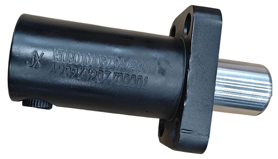
For replacements, provide the part number, key dimensions and installed photos.
Use the table below to describe the actual lift module. It separates cylinder sizing from the vehicle's navigation, traction and fleet-control functions, which belong on our AGV and mobile robotics application page.
| Category | Requirements | Purpose |
|---|---|---|
| Lift-module identity | AGV model, deck or transfer mechanism, exact component being raised, cylinder quantity and whether the motion is direct or linkage driven | Keeps the review tied to the lifting function rather than unrelated vehicle systems. |
| Load and geometry | Lifted mass, centre of gravity, acceleration, friction, guide arrangement, lever arms, cylinder angle and load at each support point | Provides the load path needed to review extension and retraction force. |
| Travel and envelope | Required deck lift, stroke, retracted and extended reference dimensions, minimum installed height and clearance around the barrel, rod and ports | Confirms that the cylinder fits throughout the complete mechanism movement. |
| Mounting interfaces | Pin sizes, clevis widths, bearing or bushing details, flange pattern, pilot diameter, fasteners, orientation and alignment tolerances | Defines the mechanical connection and helps avoid side load from misalignment. |
| Hydraulic circuit | Working and peak pressure, available flow, fluid, ports, valve block, hose routing and any load-holding or synchronization components | Connects the cylinder to the required lift time, controlled lowering and hold condition. |
| Duty and acceptance | Cycles per hour, time at raised position, ambient temperature, contamination exposure, target service interval, testing and inspection criteria | Supports review of seals, rod finish, wipers and the acceptance plan for your duty. |
We relate the required force to the effective piston area, pressure available at the cylinder, linkage ratio, acceleration, friction and design margin. Provide both normal operating pressure and any pressure peak expected during start, stop or load transfer.
We check stroke together with retracted and extended reference dimensions. For a flange-mounted unit, identify the mounting face used as the datum; for a pin-mounted unit, provide pin-centre dimensions at both mechanism end positions.
Give the required raising and lowering times and the pump flow available during each movement. On a multi-cylinder platform, include the guide layout, valve or flow-divider concept, sensor feedback and the maximum permitted difference between lift points.
We record mount dimensions, ports, orientation, hose clearance, valve interfaces and any position-sensing provision on the approved drawing. Tell us which dimensional, pressure, leakage, coating and functional checks your receiving inspection requires.
It raises a jacking deck, load platform or transfer interface. Drive and steering functions use different actuators.
No. Linkage ratio, load position, friction, acceleration and available pressure also affect the required force.
Leveling depends on load distribution, platform guides, hydraulic flow control and sensor feedback.
Do not rely on cylinder seals alone. Specify permitted drift and the required load-holding valve or mechanical lock.