|
EN
Get a Quote

PDF/STEP

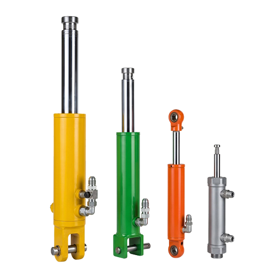
HYDRAULIC CLAMPING CYLINDER

Hold and release workpieces during machining, assembly, welding or inspection with a cylinder matched to your clamp force, stroke, installed dimensions, mounts, ports and cycle rate.
Products
Clamping Cylinder
Clamping Cylinder
  • Applicable Tonnage: 0.05 ~ 2t
  • Bore Diameter: 25 ~ 80mm
  • Rod Diameter: 12 ~ 50mm
  • Stroke: 20 ~ 1200mm
  • Working Pressure: 4 ~ 16MPa
Image 90 (1)
Image 91 (5)
Cc8c3d4ff16c2a6feb77582d98c215be 1 (1)
D38118d4ee75de51a6ae93b05eb4dd12 1 (1)
Subtract (1)
OEM/JDM
Contact Us
PRODUCT
DESCRIPTION
  • Powering Industrial Intelligence Engineered for high-frequency and high-precision operations, our automation line cylinders are essential components for modern smart manufacturing. These compact and durable actuators provide reliable motion control for critical tasks such as material lifting, workpiece clamping, and high-speed sorting. Featuring advanced sealing technology and high-wear resistance, they are designed to perform consistently in 24/7 automated environments, ensuring maximum efficiency and minimal downtime.
Fixture workholding

Design the Clamp Around Your Machine Fixture

This cylinder creates the linear motion used to hold or release a workpiece in an automated machining, assembly, welding or inspection station. The useful force at the part depends on more than bore size: your fixture geometry, lever ratio, contact point, hydraulic pressure and friction all change the force delivered to the workpiece.

We review the cylinder with your fixture drawing. Send us the part position, clamp direction, required force at the contact point, approach and clamp travel, retracted and extended installed lengths, mounting interfaces, port orientation, cycle time and circuit diagram. You can then verify the complete mechanical and hydraulic interface before quotation.

Machining and assembly fixtures

Identify the workpiece datum, contact pad, clamp direction and permitted movement during cutting, fastening or press-fit operations. Include the sequence between part loading, clamp engagement, process start and release.

Welding fixtures

Show the cylinder distance from the weld zone, expected heat and spatter exposure, hose routing and access for service. Tell us whether the clamp must remain engaged through a defined welding and cooling interval.

Inspection and test nests

Provide the maximum contact force allowed on the part, required position repeatability at the fixture and any sensor used to confirm clamp or release position. The sensor and control logic are reviewed as part of the machine system.

Replacement and retrofit

For an installed unit, send the nameplate or part number, drawing and complete measurements from the mounting datum to the rod end in both positions. Add clear photos of mounts, ports and nearby interference points.

Selection inputs

Hydraulic Clamping Cylinder RFQ Checklist

Use the table below to describe the workholding function. Broader station-level motion belongs on our automation production line cylinder application page; this product page stays focused on the clamping actuator and its fixture interfaces.

InputWhat you should provideWhat it establishes
Fixture and processStation type, workpiece, process step, cylinder quantity, clamp direction, direct or lever-driven action and the loading/unloading sequenceDefines what the actuator must hold, when it engages and when it releases.
Force and load pathRequired force at the part, contact-pad location, lever dimensions, cylinder angle, friction, external process load and design margin used by your machine teamProvides the geometry needed to relate workpiece force to cylinder force.
Travel and envelopeApproach travel, clamp travel, total stroke, retracted and extended pin-centre or mounting-face-to-rod-end lengths and surrounding clearanceConfirms that the rod reaches both positions without the cylinder becoming the fixture's hard stop.
Mounting interfacesFlange pattern, pilot diameter, clevis or trunnion dimensions, pin sizes, threaded interfaces, rod-end connection, alignment and side-load controlsDefines the mechanical connection and the datum used on the approved drawing.
Hydraulic circuitNormal and peak pressure, available flow, fluid, port thread and orientation, valve arrangement, hose routing, release timing and required hold conditionConnects force, motion time and pressure retention to the actual circuit.
Duty and acceptanceCycles per minute or hour, time clamped, ambient temperature, coolant, washdown, dust, weld spatter, inspection points and test criteriaSupports review of seals, rod surface, protection and your acceptance plan.
Holding boundary: Do not assume that trapped pressure or internal cylinder seals alone provide a safety-rated hold. If loss of pressure could release the part or create a hazard, define the validated valve arrangement and any mechanical restraint required by your machine risk assessment.
Drawing review

What We Confirm Before Quotation

Force at the workpiece

We relate the requested clamp force to effective piston area, pressure at the cylinder, lever ratio, contact position and friction. Provide the force needed at the part rather than only the machine's pump-pressure setting.

Stroke and installed lengths

We check total stroke together with retracted and extended reference dimensions. Separate rapid approach from the short clamping movement when your fixture uses both, and identify the fixed datum for every measurement.

Mounts, rod end and ports

We record flange, clevis, trunnion, pin, pilot, thread and rod-end details on the drawing. Port position must suit your hose path throughout the full fixture movement without twisting, rubbing or blocking service access.

Cycle and verification plan

Tell us the required clamp and release times, cycles per shift, dwell time, environment and planned quantity. We also need your dimensional, pressure, leakage and functional acceptance criteria before production release.

Send Us Your Fixture DataInclude the fixture drawing, part contact point, required clamp force, travel, installed lengths, mounts, ports, pressure, flow, cycle rate and hold condition.
Request a Quote
Buyer questions

Hydraulic Clamping Cylinder FAQ

What should we send first?

Send the fixture assembly drawing and identify the workpiece, contact point, clamp direction, required force, stroke, installed lengths, mounts, ports, pressure, cycle time and planned quantity. A drawing is more reliable than selecting from bore size alone.

Can bore be selected from clamp force alone?

No. We also need pressure available at the cylinder, piston-side or rod-side actuation, lever ratio, cylinder angle, contact location, friction, external process load and the design margin defined for your machine.

How should installed length be measured?

Use fixed mechanical datums: pin centre to pin centre for pin-mounted designs, or mounting face to a defined rod-end feature for flange-mounted designs. Provide both retracted and extended dimensions and state whether end stops are external to the cylinder.

Will the clamp stay engaged if pressure is lost?

Do not assume it will. Define the permitted movement, hold time and failure case, then show the load-holding valve, pressure-monitoring logic and any mechanical lock required by the fixture safety design.

What is needed for a replacement?

Provide the existing part number, bore, rod diameter, stroke, retracted and extended reference lengths, mounting dimensions, rod-end connection, port type and orientation, circuit pressure and clear installed photographs.

What changes for a high-cycle station?

Give us cycles per minute or hour, clamp and release time, dwell time, fluid temperature, ambient heat, contamination and service-access limits. These inputs are more useful than describing the station only as continuous duty.

If your project also needs other cylinder functions or a new mount configuration, review our custom hydraulic cylinder capabilities and keep each actuator's RFQ data separate.
PRODUCT
APPLICATION