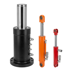


Force and travel
Confirm working force, stroke and speed at the available hydraulic pressure.

This cylinder moves parts or trays for transfer, positioning and ejection. Selection depends on push force, stroke, speed, mounting space, pressure and cycle rate.
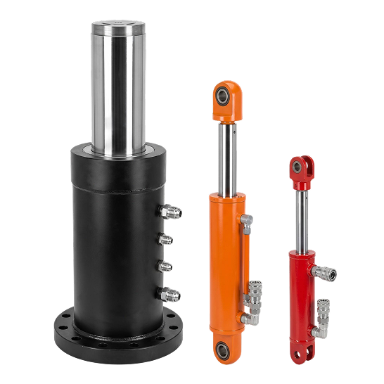
Confirm working force, stroke and speed at the available hydraulic pressure.
The carriage guides the load while cushioning or controls manage end-of-stroke impact.
Specify mounts, ports, rod connection, sensors and the available installation envelope.
| Category | Requirements | Purpose |
|---|---|---|
| Force and load | Moving mass, breakaway friction, normal resistance, process force and any impact load. | Defines the required push and pull force at the available pressure. |
| Stroke and envelope | Usable stroke, retracted and extended dimensions, clearance and rod-end interface. | Prevents interference while matching the required travel. |
| Speed and cycle | Extend and retract time, cycles per minute, dwell time and operating hours per shift. | Connects cylinder volume, flow, cushioning and thermal duty. |
| Mounting and guidance | Base mount, rod connection, alignment datums, guide arrangement and possible side load. | Keeps the rod axially loaded and reduces uneven seal or bearing wear. |
| Ports and controls | Port standard, size, direction, valve location, hoses, sensors and end-position signals. | Ensures the double acting hydraulic cylinder fits the circuit and machine space. |
| Environment | Fluid, temperature, dust, coolant, washdown, corrosion exposure and finish requirement. | Guides seal, wiper, coating and rod-surface selection. |
| Acceptance | Pressure test, leakage limit, dimensional report, traceability and documentation needed. | Aligns inspection evidence with your purchasing and quality plan. |
We compare the requested force with working pressure, return pressure and the machine designer's allowance for friction and acceleration. Rod size is reviewed together with unsupported extension and mounting orientation.
The pusher mechanism should carry side load through rails, slides or bearings. Show the guide spacing, load offset and rod connection so the cylinder is not used as the machine guide.
State the moving mass and speed near each end of travel. Adjustable cushions, circuit control or external stops can then be selected to manage deceleration without relying on an uncontrolled mechanical impact.
Fluid, temperature, contamination and exposure determine the appropriate seals, wipers and corrosion protection. Hard chrome, QPQ or other rod finishes can be specified for the actual environment.
Provide force, load, stroke, pressure, speed, duty cycle, orientation and mounting details.
No. Rails, slides or bearings should guide the carriage and resist lateral force.
Yes. Bore, rod, stroke, ports, mounts, sensors and cushions can be matched to the drawing.
Provide moving mass and speed so cushioning, valve control or external stops can be reviewed.