|
EN
Get a Quote

PDF/STEP

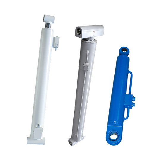
BOOM LUFFING CYLINDER

Raise, lower and position your construction-equipment boom with a luffing cylinder matched to the linkage geometry, load curve, mounts and hydraulic holding circuit.
Products
Boom Luffing Cylinder
  • Applicable Tonnage: 0.5 ~ 120t
  • Bore Diameter: 40 ~ 220mm
  • Rod Diameter: 20 ~ 160mm
  • Stroke: 100 ~ 2800mm
  • Working Pressure: 16 ~ 32MPa
Image 90 (1)
Image 91 (5)
Cc8c3d4ff16c2a6feb77582d98c215be 1 (1)
D38118d4ee75de51a6ae93b05eb4dd12 1 (1)
Subtract (1)
OEM/JDM
Contact Us
PRODUCT
DESCRIPTION
  • It is compatible with various construction machinery and equipment such as excavators, loaders, bulldozers, and road rollers. A full range of bore diameter, rod diameter, and stroke specifications are available, and the working pressure can reach up to 28 MPa. It also supports customization for various non-standard sizes and special working conditions.
  • The cylinder barrel is fabricated from premium 20# steel precision-honed seamless tubing, offering high inner wall precision and strong wear resistance. It adopts a fully automated robotic welding process, ensuring an overall structure that is stable and impact-resistant. It can perfectly adapt to high-frequency, heavy-load, and bumpy reciprocating operations on construction sites. It prevents leakage even after long-term use, ensuring a long and stable service life.
  • The piston rod is made of 45# steel base material and comes standard with hard chrome plating. It also offers a variety of anti-corrosion and wear-resistant processes such as nickel-chromium electroplating, QPQ treatment, and laser cladding. It effectively resists outdoor dust, mud, water, and sun corrosion, features excellent resistance to scratches and wear, and is suitable for various harsh construction environments.
  • We can customize balance valves, explosion-proof valves, hydraulic pipelines, and installation accessories according to customer needs. The normal operating temperature is -25 °C to +110 °C, and we can also provide customization for special working conditions such as extreme high and low temperatures to meet the engineering operation needs of different regions around the world.
Construction boom angle control

Match the Boom Luffing Cylinder to the Complete Mechanism

A boom luffing cylinder changes the angle of a construction-machine boom around its pivot. As the cylinder extends or retracts, the boom rises or lowers and the machine's working radius changes. The required force and cylinder position vary through that arc, so a bore-and-stroke match alone does not confirm the configuration.

We review your cylinder with the boom and linkage. Send us the machine model, pivot geometry, operating angles, load data, reference lengths and hydraulic schematic so we can check the interfaces that control travel, alignment and load holding.

  • Construction and material-handling boom mechanisms
  • Drawing-based OEM configurations and measured replacement matching
  • Review of stroke, pin centres, mounts, ports and valve interfaces
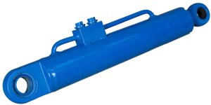
Blue construction machinery boom luffing cylinder with eye mounts and integral hydraulic tube
Existing Jiangxin boom luffing cylinder; final geometry and hydraulic interfaces are confirmed from your drawing or sample.
Selection inputs

Define the Working Angles, Load Curve and Reference Lengths

The boom linkage changes cylinder leverage as it moves. Provide the mechanism and circuit data for the full working range, not only one static position.

ItemWhat you should provideWhat it establishes
Machine and boom functionMachine model, boom type, cylinder quantity, installed orientation and intended movementConfirms that the inquiry is for boom luffing rather than telescopic extension, mast tilt or chassis stabilization.
Pivot and load geometryBoom and cylinder pivot coordinates, working-angle range, load cases and centre-of-gravity informationShows how the required cylinder force and direction change through the boom arc.
Stroke and reference lengthsStroke plus pin-centre lengths at the lowest, highest and any critical intermediate positionDefines travel and helps prevent the cylinder from becoming the mechanism's unintended stop.
Mounting interfacesEye, clevis, trunnion or flange details; pin diameters, widths, offsets and alignmentAllows both ends to be checked against the boom and base structures for fit and axial loading.
Hydraulic and holding circuitWorking and peak pressure, port thread and position, flow, hose clearance, valve block and circuit schematicConfirms connection details and whether a machine-specified load-holding arrangement must be integrated.
Duty and environmentCycle pattern, speed, shock conditions, fluid, temperature, dust, water, salt and outdoor exposureGuides review of seals, rod finish, wipers and external protection for your operating conditions.
OEM and replacement inquiries

What We Check from Your Drawing or Removed Cylinder

New boom mechanism

Share the boom and cylinder drawings, working angles, load cases, available pressure and hydraulic schematic. We can review the envelope, stroke, reference lengths, mounts, ports and valve interface as one configuration.

Replacement matching

If the approved drawing is unavailable, send the existing part number, clear installation photos and complete measurements from the removed cylinder. We will identify any missing geometry or circuit information before quotation.

RFQ data to include

  • Machine model and exact boom-cylinder function
  • 2D drawing or complete measured sample dimensions
  • Working-angle range, load cases and available pressure
  • Mounts, pins, ports, valve block, environment and quantity

Checks around the cylinder

Inspect pins, bushings, brackets, boom pivots, hoses and the load-holding components. Wear, bent structure or misalignment outside the cylinder can alter the motion path and introduce side load.

Send us your boom luffing dataInclude the mechanism drawing or measured sample so we can review geometry, travel, mounts and hydraulic connections before quotation.
Request a Quote
Buyer questions

Boom Luffing Cylinder FAQ

Is an amplitude cylinder the same as a boom luffing cylinder?

On some translated equipment documents, “amplitude cylinder” refers to the cylinder that changes boom angle and working radius. Confirm the actual machine function and linkage; “boom luffing cylinder” is the clearer English term for this page.

What measurements are needed for replacement matching?

Provide stroke, pin-centre lengths at known boom positions, both mounting interfaces, pin sizes, bore and rod diameters, port details, valve-block arrangement and installed photos.

Why are several boom positions needed?

The linkage leverage and cylinder angle change throughout travel. Lowest, highest and critical intermediate positions help define stroke, installed lengths and the load cases your engineering review must cover.

PRODUCT
APPLICATION