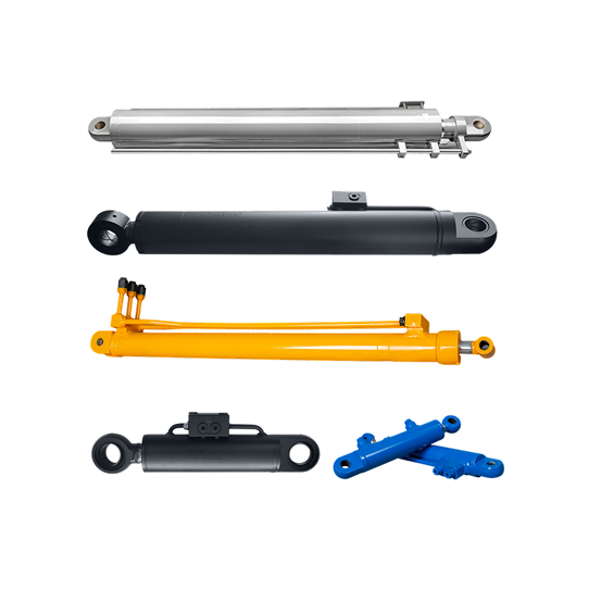
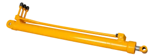
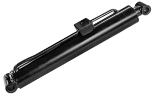


What does a horizontal outrigger cylinder do?
It moves a telescoping outrigger beam outward from the chassis and retracts it for transport. The beam guides carry transverse loads while the cylinder supplies controlled axial movement.

A horizontal outrigger cylinder extends a telescoping outrigger beam away from a crane or construction-equipment chassis and retracts it into the transport envelope. It positions the beam before the vertical support leg applies ground load; it is not the cylinder that jacks or levels the machine.
We review your cylinder with the beam guides and chassis structure. Send us the machine model, beam layout, stroke, retracted and extended reference lengths, mounting interfaces and hydraulic information so we can identify the details that control fit and travel.

A matching stroke does not prove that a replacement will fit inside the outrigger box, retain the intended beam overlap or clear the hoses at both ends of travel. Provide the complete installation data before ordering.
| Item | What you should provide | What it establishes |
|---|---|---|
| Machine and outrigger layout | Machine model, outrigger style, cylinder location, beam sections and installed orientation | Confirms that the inquiry is for horizontal beam movement rather than boom luffing or vertical chassis support. |
| Travel and reference lengths | Stroke, retracted and extended mounting-centre lengths, usable beam travel, overlap and end clearances | Defines whether the beam reaches its working position and retracts within the transport envelope. |
| Beam guides and resistance | Guide-pad arrangement, beam mass, expected extension force, operating slope and known binding points | Separates normal axial demand from resistance caused by worn guides, distortion or misalignment. |
| Mounting interfaces | Anchor and rod-end type, pin diameters, widths, offsets, threads and access for assembly | Allows both ends to be checked against the chassis and telescoping beam structure. |
| Hydraulic connections | Working and peak pressure, fluid, port thread and position, flow, hose path and available clearance | Confirms connection compatibility and hose movement through the full stroke. |
| Duty and environment | Cycle pattern, temperature, dust, mud, water, salt exposure and storage orientation | Guides review of seals, wipers, rod finish and external protection for your operating conditions. |
Share the chassis and beam drawings, travel sequence, expected extension force and hydraulic schematic. We can review the cylinder envelope, reference lengths, mounts, ports and hose routing as one configuration.
If the approved drawing is unavailable, send the existing part number, clear installation photos and complete measurements from the removed cylinder. We will flag any missing guide, anchor or circuit detail before quotation.
Inspect the beam, guide pads, rollers, anchors and hose carriers. Worn guides or a distorted telescoping box can increase sliding resistance, change alignment and side-load a replacement cylinder.
It moves a telescoping outrigger beam outward from the chassis and retracts it for transport. The beam guides carry transverse loads while the cylinder supplies controlled axial movement.
No. This page covers horizontal beam positioning. A construction-equipment support-leg cylinder extends vertically to transfer load to the ground and level the chassis.
No. A boom luffing cylinder changes boom angle and working radius. A horizontal outrigger cylinder changes the reach of the chassis outrigger beam.
Provide the machine model, stroke, retracted and extended mounting-centre lengths, both end interfaces, ports, pressure, hose routing, beam-guide details and clear installed photos. You can also browse the construction machinery cylinder range.